Tuesday, May 29, 2012

Archtop Guitar Build - Fret and Neck Work

I left the neck as a solid block because it would make support for seating the frets very easy.  I usually seat my frets with a dead blow hammer but I got a fret press with 12 inch radius insert from Bob when I bought the radius beam.  Wow, what a nice tool!  The frets seated well and easily but the fret press really shined in the area over the neck extension.  Just shim up a support and gently press the frets into place.

Now that I don't need the support of the neck block, I trimmed the neck to shape, added the extension for the nut channel as well as ears for the headstock.  We're getting close now...

Saturday, May 26, 2012

Archtop Guitar Build - Fingerboard and Neck Extension

The neck for this guitar is made from a single piece of maple so there are a few aspects of this type of construction that I will take advantage of.  The neck was planed square, the headstock angle was cut and a channel was made for the truss rod.  I am using a Stewart Mac "Hot Rod" dual action truss rod for this guitar.  I purchased a spiral cut router bit that was exactly the same size as the truss rod width so the fit would be perfect. A dovetail was cut into the end of the neck to connect it to the body.

The fingerboard extension was something that I thought about long and hard.  The plans call for cutting a 5/8 inch rabbet into the end of the neck and then trimming away about half of the material to thin it out enough to allow the neck to sit low enough to allow a distance of 3/4 of an inch to be obtained if a straightedge is held over the fingerboard and extended over the body to where the bridge sits.  The problem with this way of attaching the neck extension is that you remove a perfectly cut dove tail with the rabbet and then have to re-cut that dove tail into the bottom of the fingerboard extension and this entails carving into a blind corner.  I thought about this and came up with this alternative.  A dovetail could be cut into fingerboard extension instead and this strong joint could be used to attach the extension.  This would allow you to fit the neck into the body and remove the fingerboard extension for frequent trimming of the extension to get the fit just right.  This is what the neck and fingerboard extension joint looked like.  The truss rod is also in place.


The fingerboard was run though my model making table saw to cut the fret slots and the taper was also cut into the sides.  Plastic binding material was run around the edges and mother of pearl inlays were prepared.  I really liked the inlays shown on the plans but when I looked around, I couldn't find ones that matched them.  I bought a set of generic block inlays (like on a Les Paul Custom) and cut scallops into the edges to make them "hour glass" shaped.  I then cut them at a 66.6 degree angle and fitted ebony strips between the two pieces and super glued the three pieces together so I had to only make one recess for the inlay rather than two.  These were glued in using epoxy with a couple of drops of amber and black Stew Mac Color Tone dye added.  This makes the epoxy "ebony" colored and any imperfections in the routs are magically hidden.  The finger board was set in place and a couple of pieces of fine wire were drilled though two fret slots to act as indexes for the glue up.  I used hide glue for this so that if I ever needed to replace the fingerboard, I could steam it off.  Here is the glue up.
The fingerboard is a uniform 1/4 inch thick so a 12 inch radius must be cut into the surface of it.  I bought a 12 inch Stewart Mac radius block from Bob Gaffney (be sure to check out his very well done archtop blog) and installed two shooting boards into the sides of the neck block.  This is one place where altering the neck building process from that described in the book works out well.  By leaving the block intact I can easily mount it in a workmate, hold the fingerboard in its final position and also mount the shooter boards with screws so that the radius block always travels straight down the fingerboard with no deviation left or right.  Here is the neck and fingerboard after 100 grit sanding to a 12 inch radius.

Sunday, May 13, 2012

Archtop Guitar Build - Disaster Strikes

Next up was routing the channels for the bindings.  I used a jig that I had built for binding the ukes and I had no problems routing the channel for the top plate.  When I was working on the bottom plate channel, I noticed that the body of the guitar had a lot more resistance to pushing it forward after the bit had passed the neck block.   I pulled the guitar body away and found that the spiral cutting bit had pulled itself forward in the chuck and had routed the channel about 1/8 of an inch too deep!  The side of the body was veneer thin over this channel and had broken though in one area.  I was sick!

When a disaster strikes, the first thing you want to do is fix it quickly but the best thing you can do is to back away and come back another day.  Taking time to think through the problem helps avoid making the problem worse by trying a quick fix.  There were a lot of options available.  My first thought was to fill the bad route with ultra-thin model airplane plywood to stabilize the side, that's the darker brown material in this photo.   I then planned on using matching maple veneer to cover the plywood core but I knew that I would never be happy with this kind of repair.  It was time to gear up for major surgery.

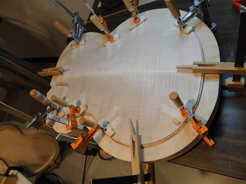
I sawed the back plate off of the guitar and stripped out the linings for this plate.  I then made new linings, installed them and leveled them out.  Here is the body with new lining, placed back in the building mold just before the back plate was glued on.
The new total depth of the body is 2 3/4 inches which is at the low end of acceptable per the Benedetto book.  The only problem is that the end pin hole is now closer to the back plate than to the front but this was a small price to pay for a better repair.  Here is the back plate being glued in place
I then invested in the Stew Mack binding router set-up.  It is very pricey but it works well and I knew that if it saved me from having to go through another major set-back it would be worthwhile.
 The new channels were clean and true.
 Plastic binding was installed on the problematic back plate and this is the end result.

 Here is the front plate with the bone insert for the tail piece strap.


It is nice to be back in business...


Monday, May 7, 2012

Archtop Guitar Build - Body Assembly

The back plate was placed under the sides and a coat of thinned shellac was applied to seal the back plate and sides.  The inside of the back plate was lightly sanded and the top plate was placed into a gluing caul and glued to the sides which were held in place in the body mold.  The top plate then had a coat of shellac applied and was lightly sanded.
 The top plate and sides were removed from the mold and placed back into the gluing caul and the back plate was glued in place using a second caul.  Once again clamps were placed to provide even pressure around the perimeter.
 The sides and back plate were intentionally over-sized by about 3/16 inches to prevent the possibility of having them be too small for the sides (that would be really bad...).
 The plates were sized to the sides using the spindle sander with a standoff on the table to make sure that only one plate was sanded at a time.  Here is the assembled body waiting for binding channels.

Wednesday, May 2, 2012

Archtop Guitar Build - Linings and Bracing


My table saw is very high precision but the blade can't be tilted so I had to figure out a way to cut the kerfs and the incline.  I squared up quarter-sawn spruce and used this jig to make the saw kerfs every 1/4 inch on the flat stock.  The small spline is inserted into the previously made cut and indexes the cuts with good precision.
Now that the kerfs are cut, the wood is then run through the spindle sander with an inclined fence to make the angled edge.
 Here are the finished pieces.
 The linings were then installed around the perimeter with cross braces placed at set distances as per the plans.
The quarter-sawn spruce braces for the top were marked using the jig below.  A 0.5mm pencil lead was placed through the hole drilled in the side of the jig and the rounded end was run across the inside of the top so that the jig could scribe a line a fixed distance above bottom on each side of the brace.  The material below the line was sawn off and the brace was trued up so that it fit at all points across the brace.  This is very tricky to do because it is running across an area that is anything but flat and true.  It slopes in all directions but if you remove small amounts and test fit, frequently, you can get a precise fit.
The braces sit a long way from the edges of the top plate.  I took advantage of the "f-holes" and threaded some cam clamps that I had made for my uke build through them to clamp the brace.
 Small pieces of lining were placed over the side braces to complete the linings.