Tonight was fret installation night. The fret wire was cut to be a little wider than the fingerboard width. Because the finger baord has a binding on it, the fret wire needed to be under cut on the ends to allow it to hang over the binding material. A Stewart Mac fret nipper worked well for this and a fine file was used to clean up any remaining tang.
A fret hammer was used to seat the wire and a fret leveler was used to make the fret edges even with the binding as well as create the 30 degree beveled profile on the edge. A fine file was used to dress the fret edges and the fret crowns will be leveled on the uke since there might be changes to the flatness of the fret board once it is mounted.
Here is a photo of one of the mother of pearl palm trees for the head stock.
These are a series of articles detailing projects that I've built. Click on the Blog Archive arrows to expand the months and see more articles that posted here...
Showing posts with label construction. Show all posts
Wednesday, November 2, 2011
Sunday, October 30, 2011
Ukulele Build Part 4
Plastic bindings were added to the sides of the finger boards. Each fingerboard needed to be reduced in width to allow the plastic bindings to fit the neck width. I tired tight bond as a glue but this didn't work well so I switched to thin CA glue and this worked very well. The plastic was pre-bent to fit the profiles of the fingerboard edge and the CA bonded instantly and firmly. Scrapers and sandpaper were used to make the binding flush with the fingerboard profile.
Thursday, October 27, 2011
Ukulele Build Part 3
Here is the ebony fingerboard with mother of pearl inlays. The fret slots were cut with a .020 slitting blade in my Byrnes table saw so everything is good, square and true. I used a dremel with the Stewart Mac base to make the inlay recesses (please see the inlay post on this blog for more details). I also used a down cutting bit to level the MOP to the fingerboard after the epoxy dried. This saved a lot of hand finishing and time plus it protected the finger board from sandpaper dings in the leveling process. The other photo is of the head and tail blocks for the body.
Monday, October 24, 2011
Ukulele Build Part 2
This build might move along a little slower than most others because this one is going up live as the build goes on as opposed to most of the others which are retrospective. Tonight the sound hole and route for the rosette were cut. A Stewart Mac router base was used along with a 1/4 inch cutter to make the rosette route. A hole was drilled through the router base and the router and bit were nailed through the uke front with the nail forming a pivot for the router assembly. The same was done to cut out the sound hole. Masking tape was used to cover the router base to protect the top from any scratches. Both routes were perfectly round.
Sunday, October 23, 2011
Ukulele Build Part 1
I'm in the process of building a pair of Soprano Ukuleles, one from a kit that I bought from Stewart Mac and the other from scratch based upon the kit. Last year for my birthday, my youngest got me a mahogany board so decided that I should turn it into a uke. Here are photos of the milled materials for the sides, fingerboard, top and back and necks before and after shaping and laminating the face of the headstock.
Wednesday, October 5, 2011
How to make rope
This is a machine that can be used to make rope for models and a larger version can be used to make full scale rope. It is called a "rope walk" and works on the principle that if you take three strands and wind them up individually in one direction, they will then release their tension by winding around each other in the opposite direction and the two forces will cancel each other out and the result is stable rope. This is what the machine that I use looks like. Turning the crank on the machine on the left causes all three strands to be spun at the same time.
Here is the machine in action. The three strands are attached to the machines and are spun by the machine on the right. A wooden egg with three grooves cut in it serves a the bobbin and holds the strand apart as they spun. Once the proper amount of tension is built up, the machine on the left is turned in the opposite direction and the result is shown below..Here you can see the finished rope used in a model. It looks very realistic in scale and can be made to whatever diameter is needed. By putting multiple "ropes" on the machine, larger hawsers and cables can be made for anchors and such.
Saturday, June 11, 2011
Pinewood Derby 1966 AC Cobra
Here are a couple of photos of a 66 AC Cobra that I made for a pinewood derby a few years ago. I no longer have the car since I gave it away to a Cobra fan. The paint job is candy apple red over a white base with several layers of clear coat lacquer sprayed over it and buffed out.
Thursday, May 19, 2011
Folding wooden book stand
This is this year's birthday present for my wife. She likes to do her Bible study at the table and I've noticed that she tends to prop up her Bible when she is studying so I designed and built this for her birthday. Because is fold up it can be taken with her wherever she goes.
The stand is made of maple and the wooden hinges were made with individual pieces since I don't have a drill with the length to make a single pass for drilling the hole for the brass hinge pins. The finish is shellac that has been buffed with 0000 steel wool for a fine matte finish.
Labels:
construction,
Finishing,
Maple,
Scratch Built,
Shellac,
Wood
Friday, January 7, 2011
Scratch Built 1:12 Peterboro Canoe Conclusion
The hull is now surprisingly strong for its light weight and will get even stronger once the internal frames are added. Start by milling strips that are 1/16 by 1/32 inch in cross section.
These are soaked and bent over the approximate strongback frames. This will prevent them from kinking when inserted into the hull.
They are placed into the hull while damp and thin CA is used to glue them in place.
A strip of plastic works as a spacer and the frames are glued into place the whole length of the hull.
Once all are in place, trim the ends and sand flush with the sheer plank.
| ||
Three short segments of strip are used to finish off the planking of the stem and stern and a gentle curve is carved and sanded into these strips. The stem and stern pieces are trimmed down and a crown is made into the tops of these.
The decks are glued in place with a slight separation between the deck pieces at the far ends of these. This will be covered by a cap on top and a false keel at the ends.
As can be seen in this photo, there is plenty of excess material for forming the overhang on the hull.
Cap rails are cut and installed between the ends of the decks.
The interface between the cap rails and the decks are cleaned up and a gentle camber is sanded into the tops of the decks.
An even overhang is shaped in the cap rails and decks.
Deck caps are installed and trimmed to size.
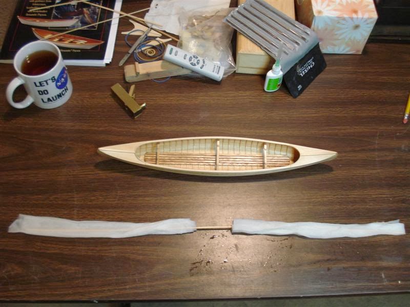
Here is a very effective method for soaking wood that works well if you don’t want to get a large container out to hold the planks. If the wood is very stiff and doesn't want to bend well, the water soaked plank/paper towel assembly can be micro-waved to steam the wood. I've used this technique several time with uniformly good success.
The false keel is bent to shape and installed onto the hull using rubber bands attached to the thwarts to hold it in place while the glue dries.
The cockpit combings are formed using a bending jig made of MDF and then are installed into place.
Trim and profile the combings once they are attached to the canoe.
Paddles can be made to accent the canoe display. For this particular canoe I chose traditional otter tail paddles. First find a pattern that you like and size the paddles to an appropriate length. In this case they end up being around 5 inches long. The various stages of production are shown here.
Make a pattern and trace out on basswood, cut out using a new and sharp knife. Use a plane or other tool to thin out the blade of the paddle.
Since I turn out the shafts on a drill press I carve a round section to insert into the drill press chuck. Turn the shaft.
Finish off the hand grip and smooth off the interfaces between the handle, shaft and blade.
Here is a photo of the completed canoes. The one in front has mahogany trim and the one in back cherry. The presentation plate has been placed on the first canoe while the second is still awaiting a suitable event for presentation. I hope that you've enjoyed following along.
Saturday, December 11, 2010
Kayak Construction Part 1
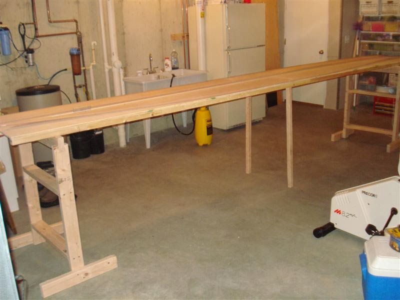
The first step was to build a pair of saw horses out of 2x4’s. These saw horses have removable top bars and will later be fitted with nylon webbing to create a sling for holding the formed kayak hull. I also built a 16 foot long table from ½ inch plywood with 2x2 furring strips screwed on for support. After adding a set of middle legs, this is what the horses and table look like.
The hull sides come in pieces because shipping a 17 foot long segment of hull is impractical. A special 4mm mahogany plywood called Okoume is used for the hull because it is engineered to have no voids in it. Any void would cause a weak spot in the hull which could fail during the bending process or worse, on the water. Scarf joints are made at the ends of the hull panels for a strong joint.
The plywood table is used to align and glue these panels together. A baseline is made with a length of thread. The left and right panels are stacked and specific offsets are measured from the thread baseline. When the panels are in the exact location, a few brads are nailed through the panels about two feet from either side of the scarf joint. This allows the panels to be lifted for gluing. Clear tape was placed along either side of the joint to allow easy removal of excess epoxy.
MAC epoxy is mixed in a 2:1 resin to slow hardener ratio. The epoxy will be clear and have a consistency of light syrup at this time.
Cell-O-Fill powder is mixed into the resin until a “mustard” consistence in achieved.
This mixture will be the glue that is used to join the panels together. Sheets of clear plastic were placed between the layers of hull and epoxy was applied to both gluing surfaces. The hull panels were clamped for 24 hours to allow for proper curing of the epoxy.
At the same time lengths of 1 x 3/4 inch boards were scarf joined together to form the sheer clamps.
The sheer clamps were glued on to the upper edge of the side hull panels. These sheer clamps are added to provide extra area for gluing and nailing the deck to the hull. They are placed ¼ inch proud to the top of the side panels so that the radius of the deck camber can be planed into them later in the assembly process. The side panels were placed back to back and clear plastic sheeting was put between them. The same mustard consistency epoxy/cell-o-fill mixture was made and applied to the sheer clamps and side panels. Every clamp and clip in the shop was used to ensure a tight bond.
Before the clamps were removed, a series of 1/8 inch holes were drilled in the ends of the side panels. These panels were then held together with short lengths of 18ga copper wire.
The bottom hull panels were stacked and holes were drilled 4 inches apart around the perimeter of the panels. The keel line of these panels was stitched together.
The hull sides were placed upon the horses and a spreader was constructed to hold the maximal beam width of 24 inches at a set distance from the bow as specified in the plans.
The bottom hull assembly was opened like a book and placed upon a set of boards that spanned the awaiting hull sides.
Starting at the bow, a series of holes were drilled into the side panels to match the holes already drilled in the bottom panels. Copper wire was used to stitch the bottom and side panels together. Here is what it looked like about half way done.
Here is the hull almost stitched together.
It was very exciting to watch the hull “magically” turn from flat panels into a recognizable kayak hull.
Go to part 2
Subscribe to:
Posts (Atom)